Capability
Cable Overmolding and Insert Molding Support
Overmolding helps integrate strain relief, cable routing, sealing review, and application-specific geometry into a cable assembly when the connector, cable, material, and tooling requirements are clear.
Request a Quote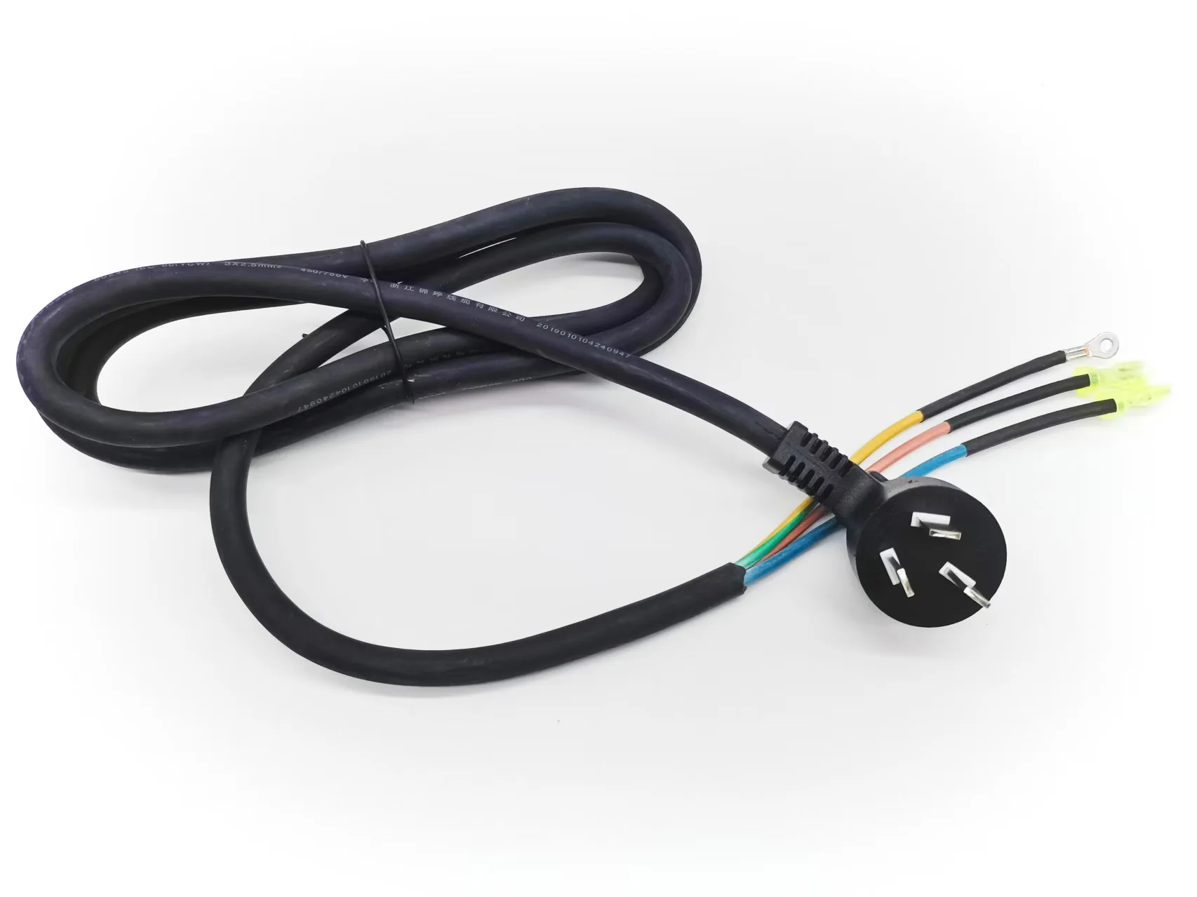
Buyer questions this capability answers
- What connector or cable exit needs strain relief?
- Is the overmold geometry already defined in a drawing?
- Which material, hardness, color, or marking is required?
- Does the part need a gland, stop, breakout, Y junction, or T junction?
RFQ requirements
- Drawing or sketch
- Connector part numbers
- Cable type and length
- Overmold geometry
- Material preference
- Quantity
- Testing and certification requirements
Control points
What must be defined before production release
Control points must be defined from the drawing, material, connector, test method, and acceptance criteria for the specific project.
| Geometry | Drawing, 3D model, sample, or sketch defines molded shape and cable exit. |
|---|---|
| Material | PVC, TPU, TPE, silicone, or other material reviewed against application environment. |
| Sealing | IP, airtightness, or waterproof expectations require customer-supplied criteria and validation path. |
In-house scope
Manufacturing steps MTTJ can review
Exact process scope depends on the drawing, material, connector, and testing requirements supplied during RFQ.
- Vertical overmolding / insert molding
- Wire cutting
- Wire stripping
- Terminal crimping
- Soldering
- Electrical testing
Boundary
Partner sourcing or engineering review
Partner sourcing or additional engineering review is identified during RFQ when a requirement sits outside the ordinary in-house process path.
- Horizontally injection-molded housings requiring horizontal molding machines
- PCB assemblies / circuit boards
- Project-specific certified components or plug assemblies supplied through qualified sources
Process
How the requirement moves through review
These steps show the normal review path from customer input to production release, inspection, packaging, and shipment preparation.
- 1
Review drawing, connector, cable, and application requirements
- 2
Confirm material preference, geometry, and tooling path
- 3
Prepare cable and connector subassembly
- 4
Run vertical insert molding or overmolding workflow when suitable
- 5
Inspect molded geometry and complete electrical testing
Related products
Product pages connected to this capability
RFQ support
Ready to discuss a custom cable assembly?
Send drawings, specifications, quantity, testing requirements, and documentation needs. MTTJ will review the RFQ and respond by email.